Bodywork - Doors, Boot & Bonnet
The Doors
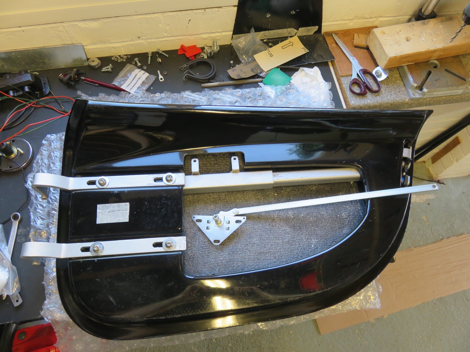
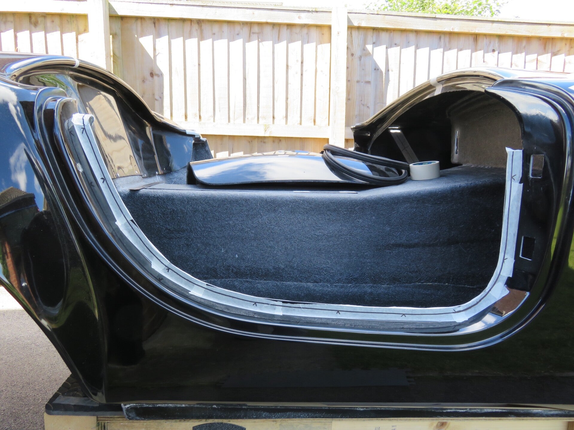
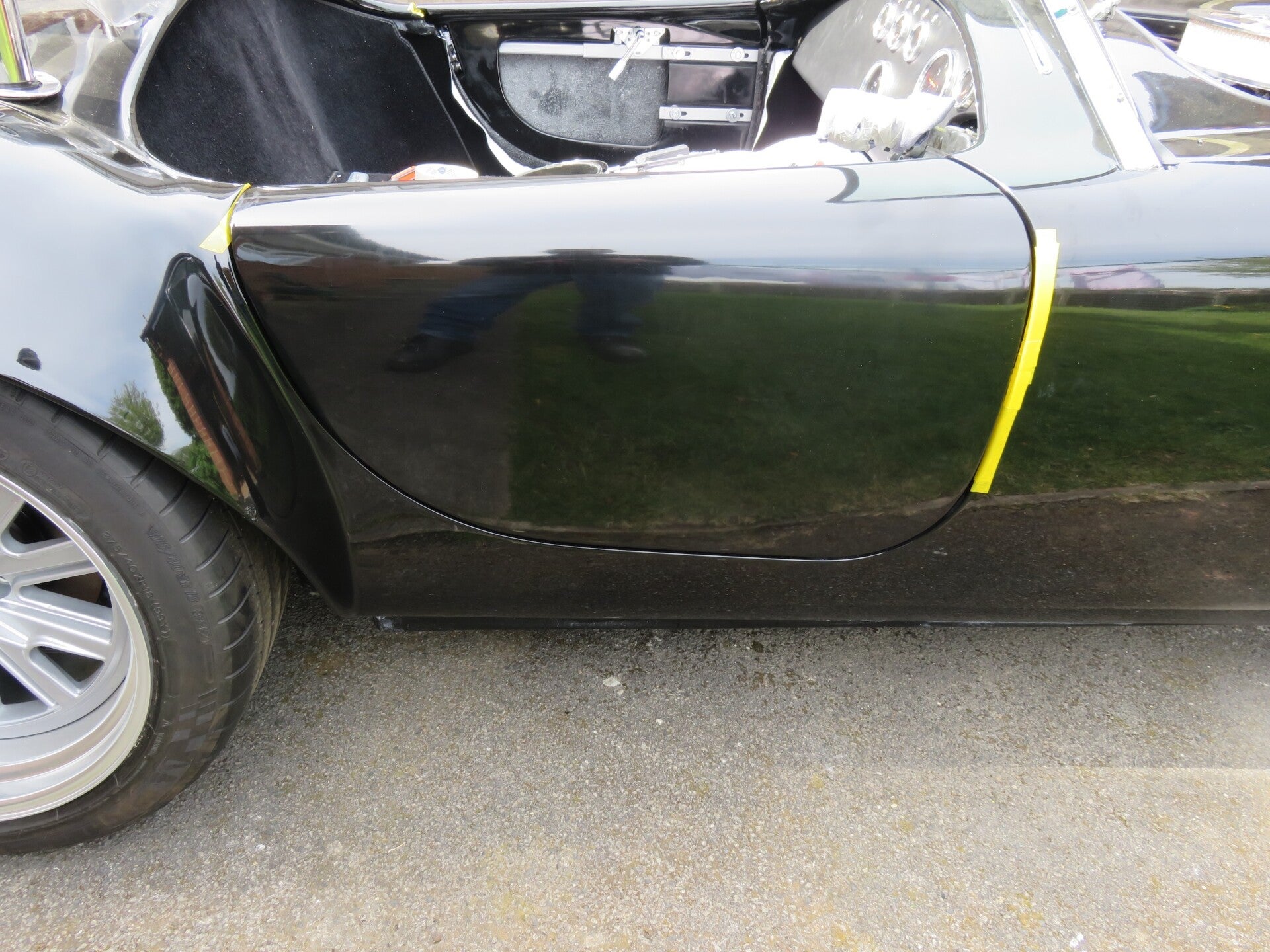
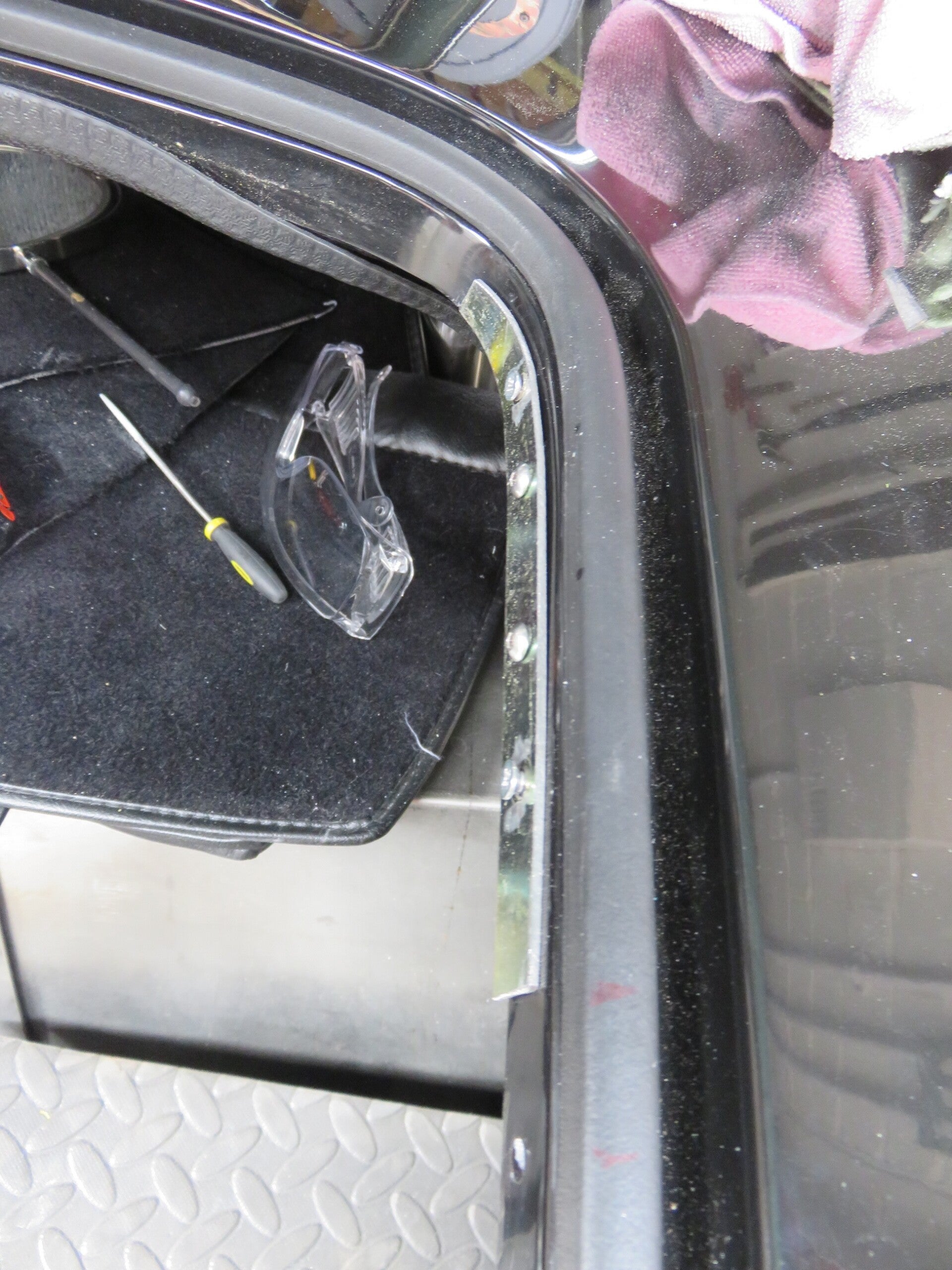
Frames: The first job was to trim and neaten up the inside edge. Using the rubber trim as my guide, marked up and cut the unnecessary off with the Dremel and then finished with a light filing. I did notice the GRP varied slightly in thickness and bobblyness along the edge, so I had to file in places to make it more uniform.
Fitting: Fitted the hanging bracket and the door hinges. Bolted the door loosely in place and adjusted the positioning. Not too fiddly, but had to adjust and move the body hanging bracket to get the ‘swing’ right, which took time, and I did have to round the top outside edge.
After it was in place, I marked the frame and door with a dab of paint to show what lined up and where… Don’t need to go through this again in the future if I have to take it off for some reason…


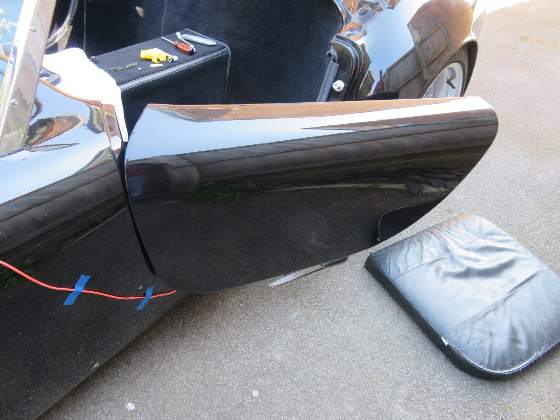
The Boot

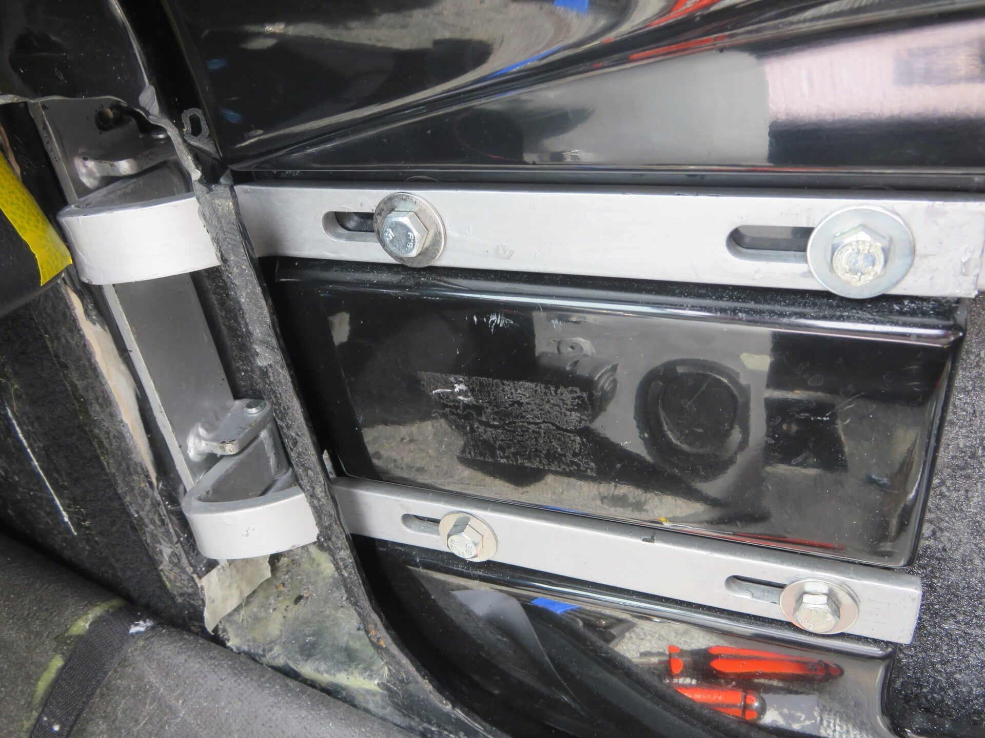
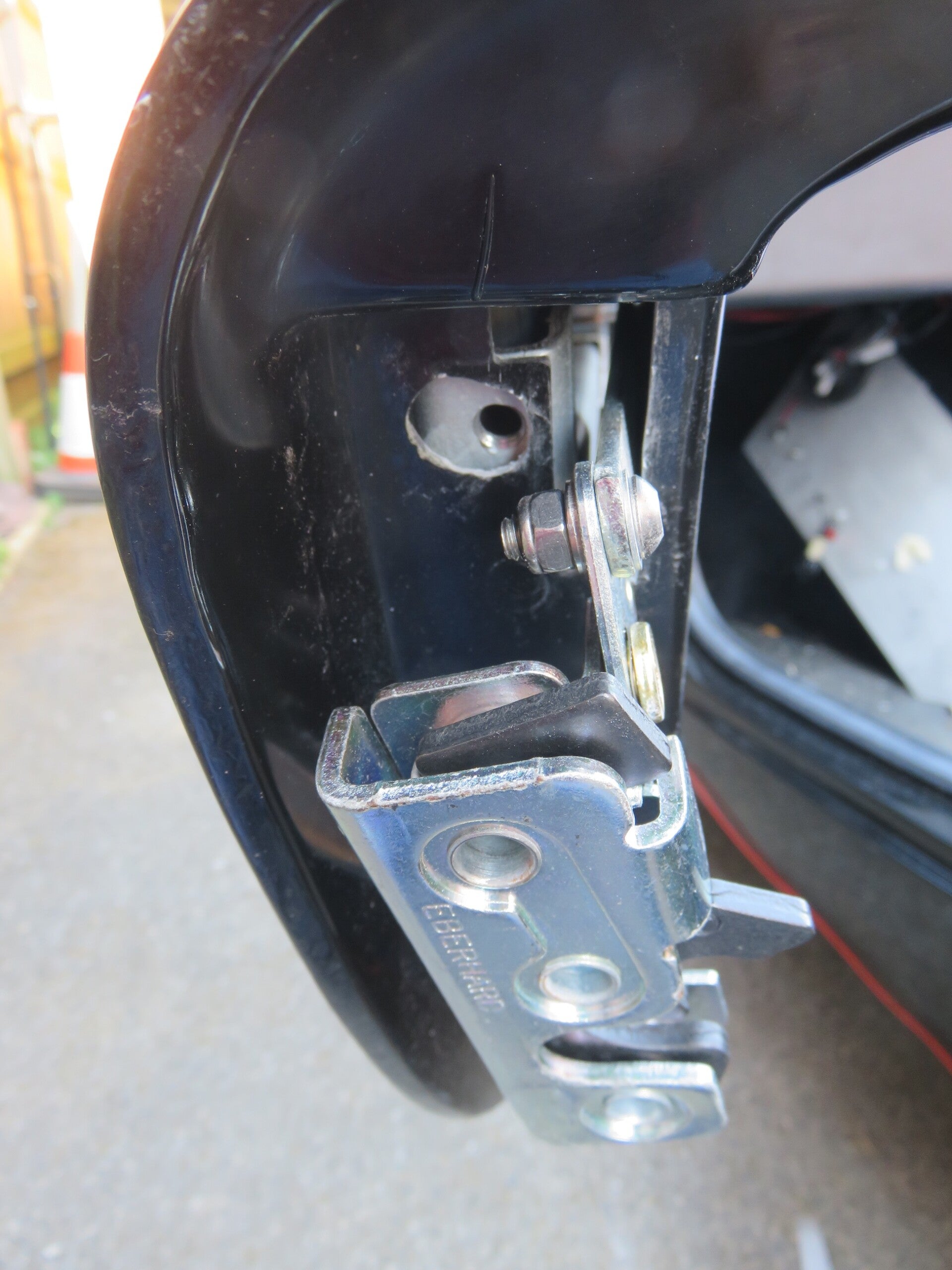
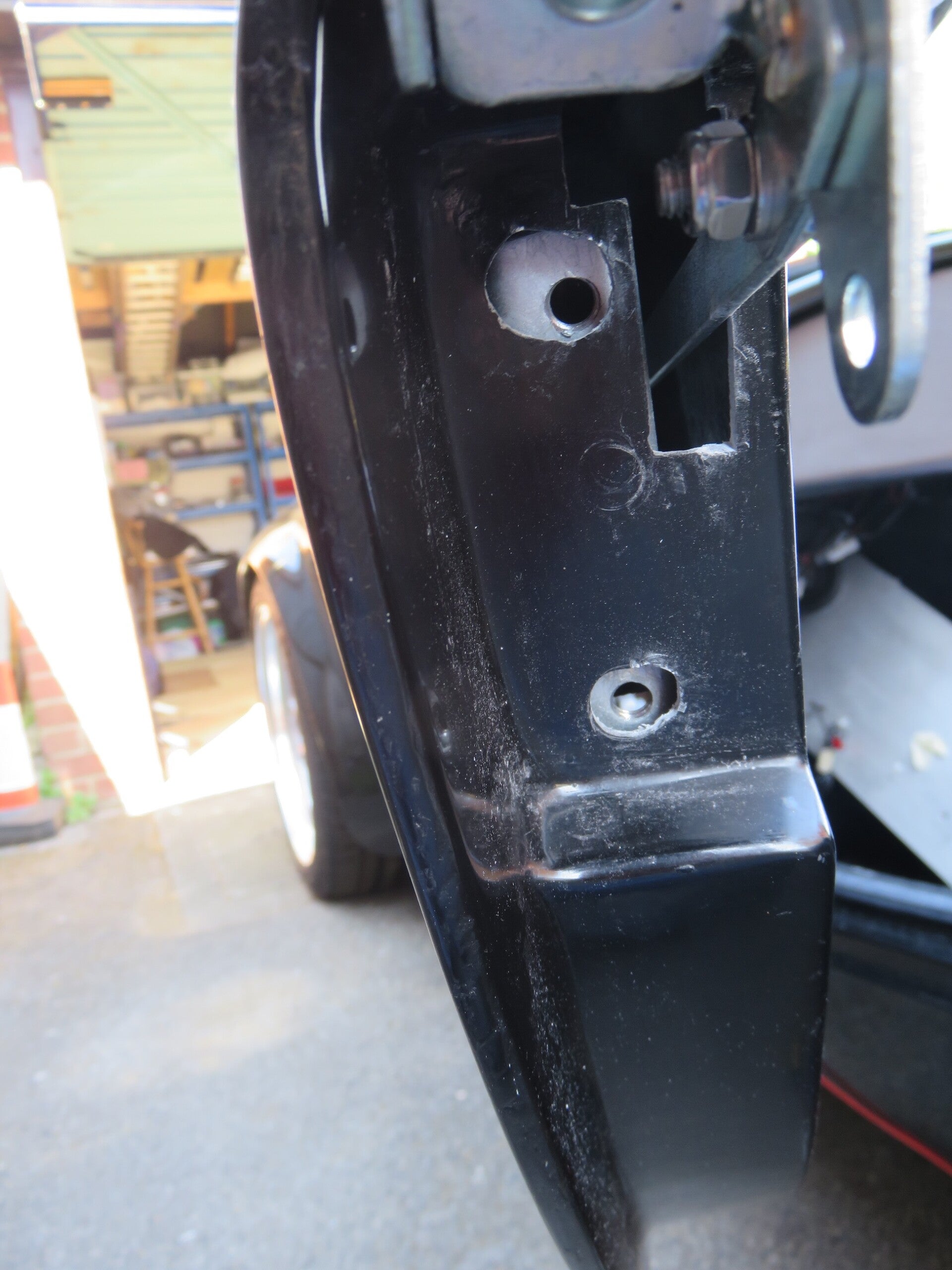
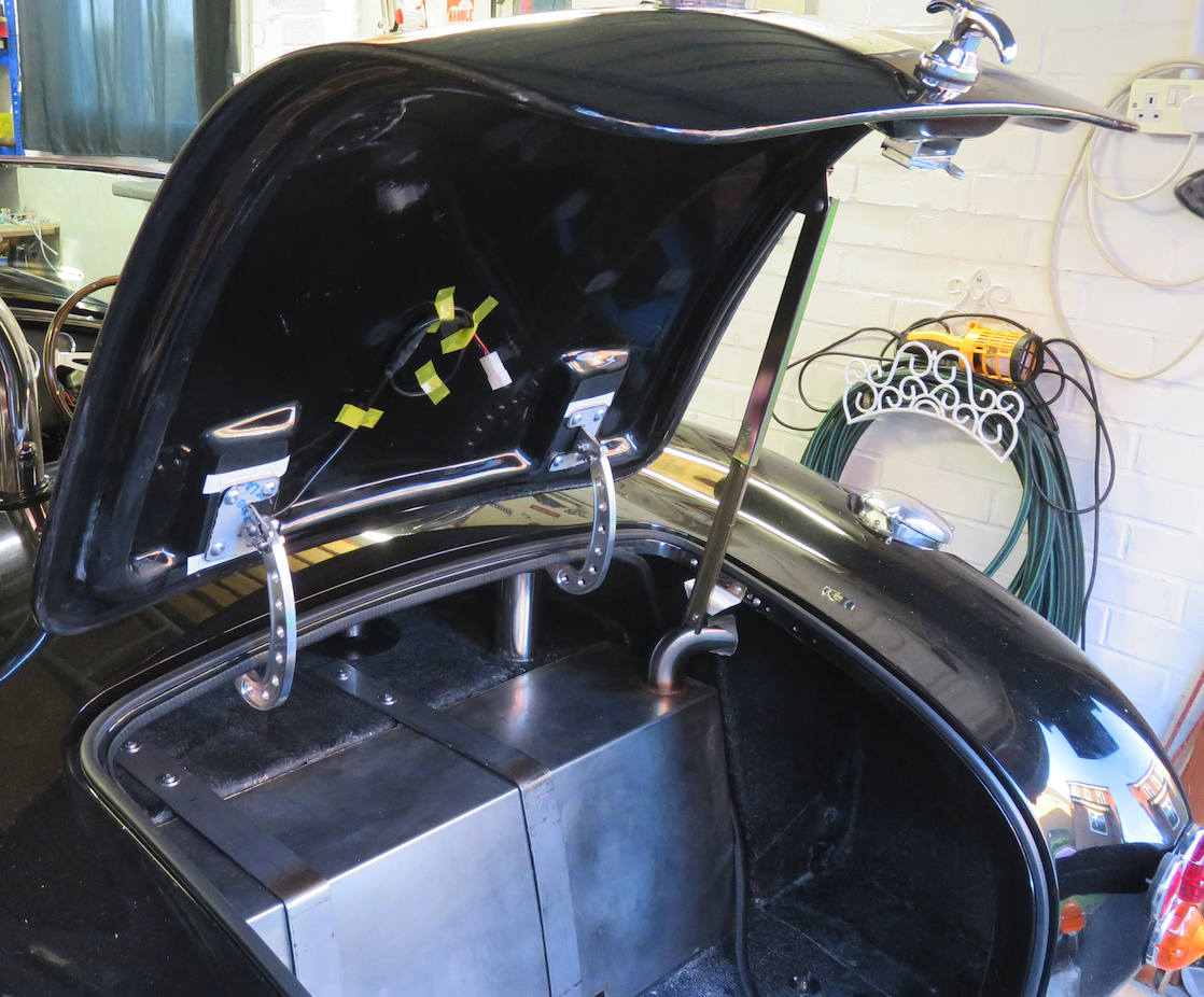
Boot Hinges: The hinges are a work of engineering art. Couldn't resist them. Quite a straightforward fitting; just trim the spacing flange to size, adjust the hinge spacing with packing washers, bolt them in place, attach the boot and adjust for flatness as necessary.
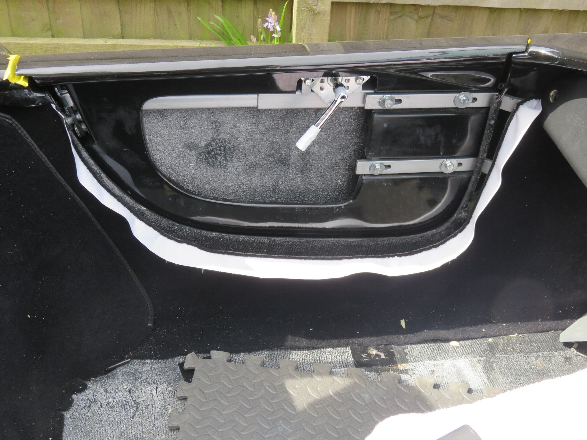
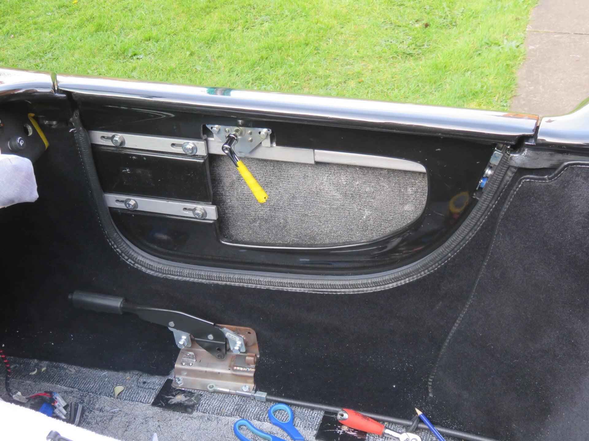
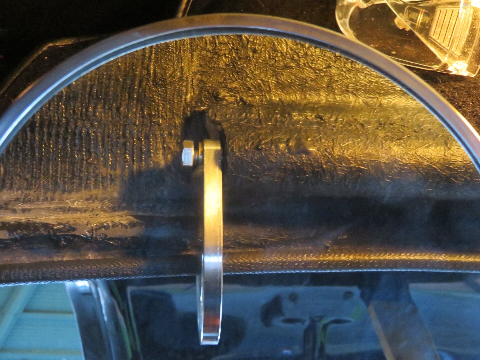
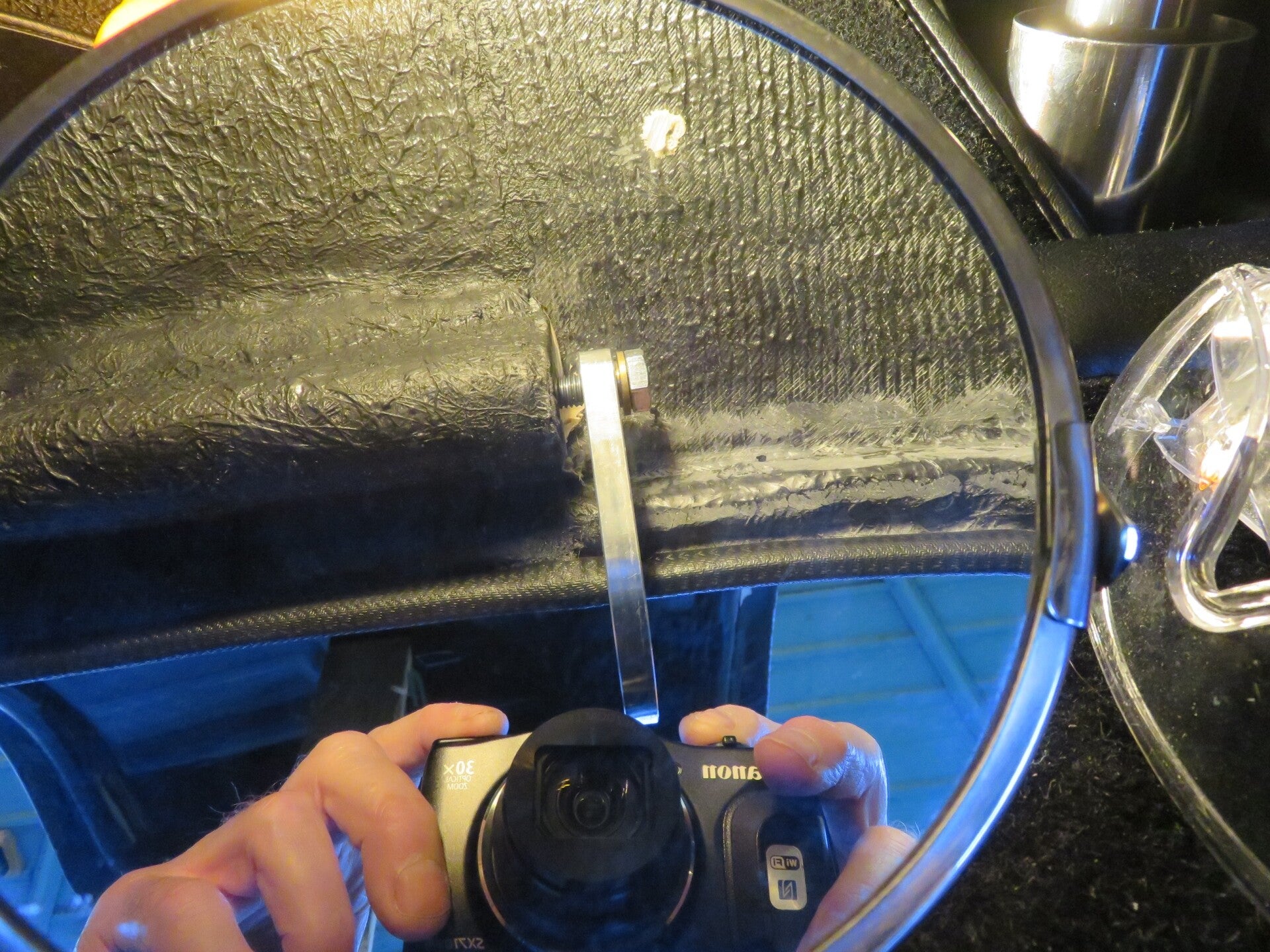
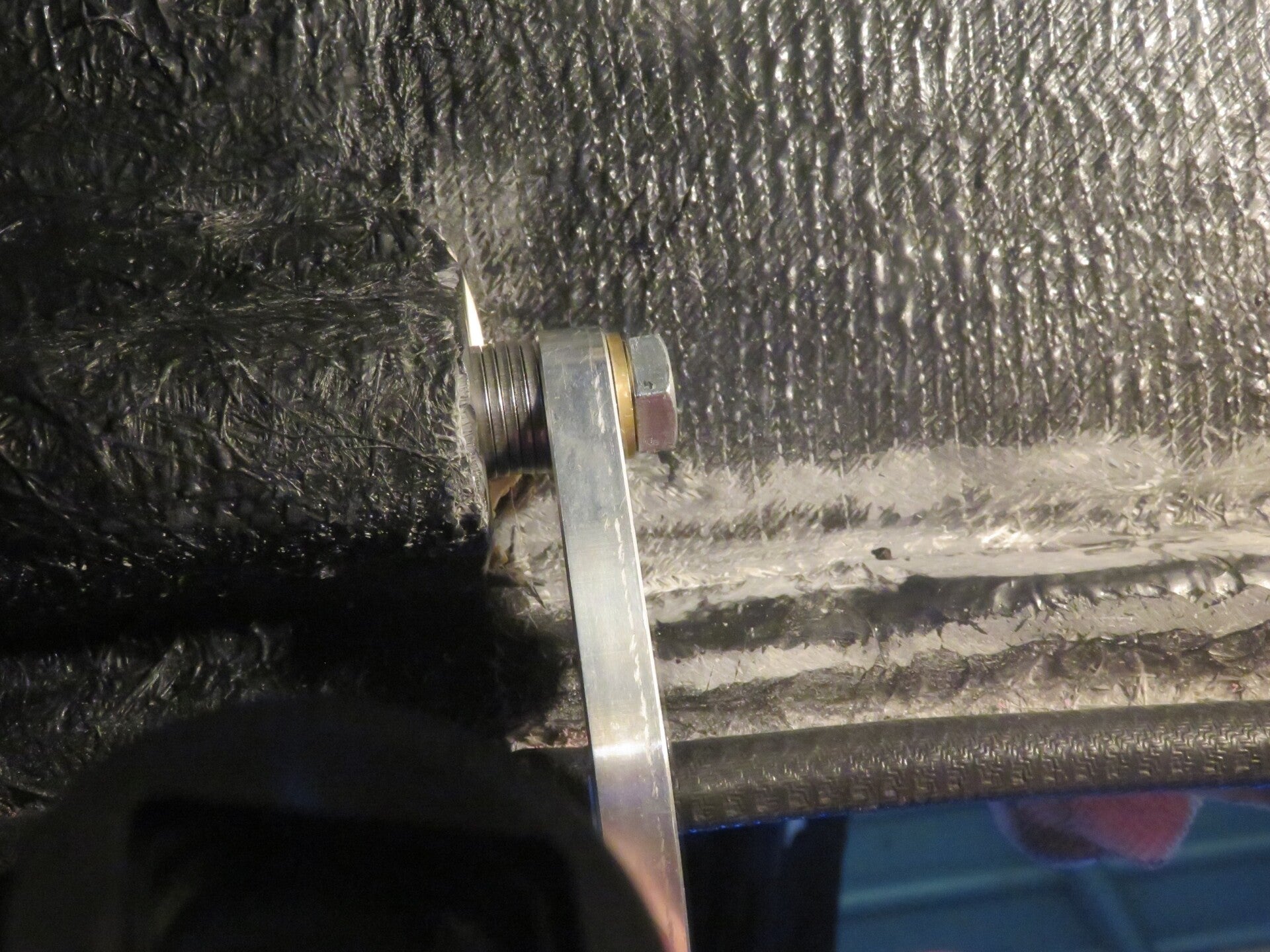
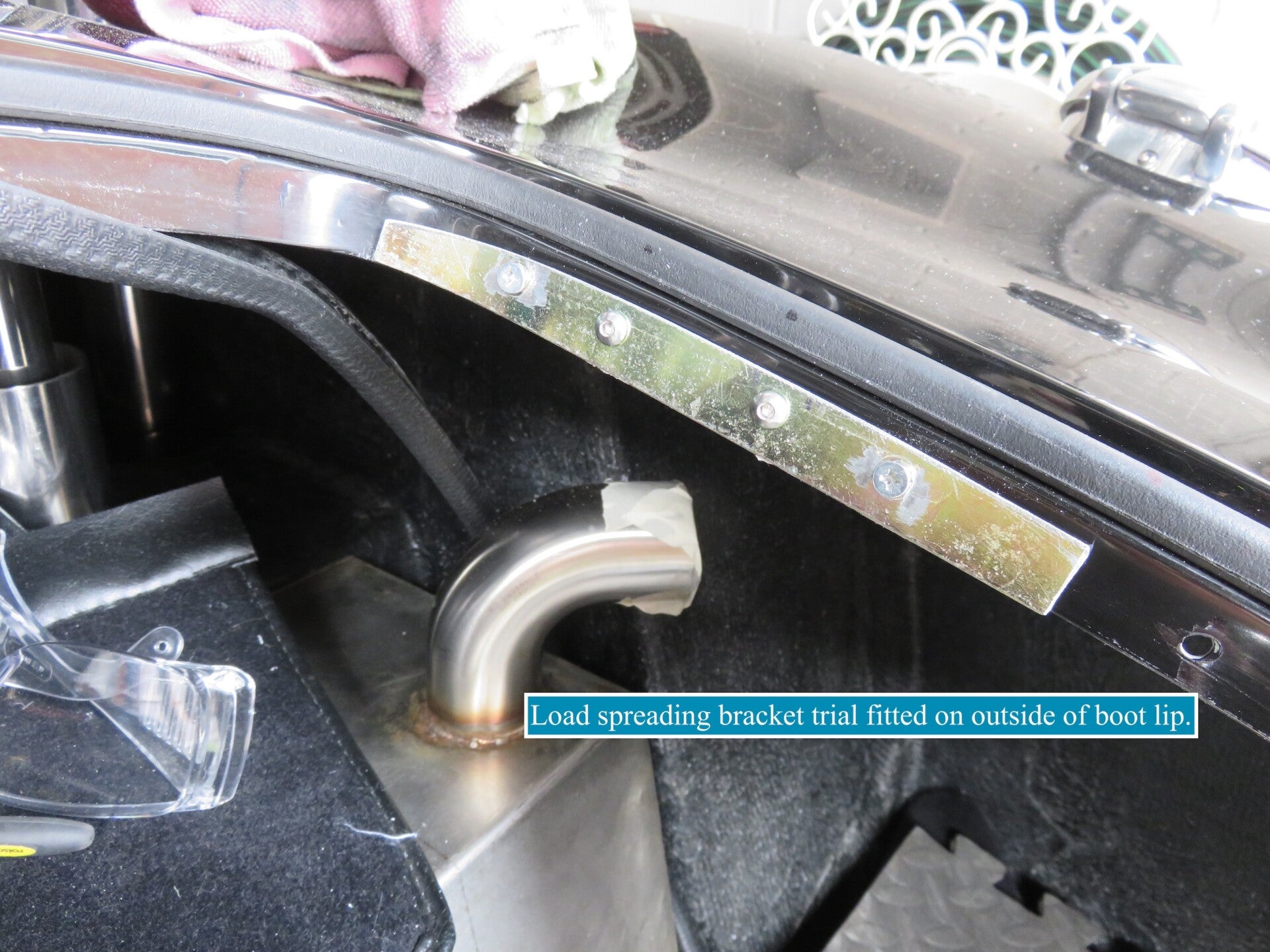
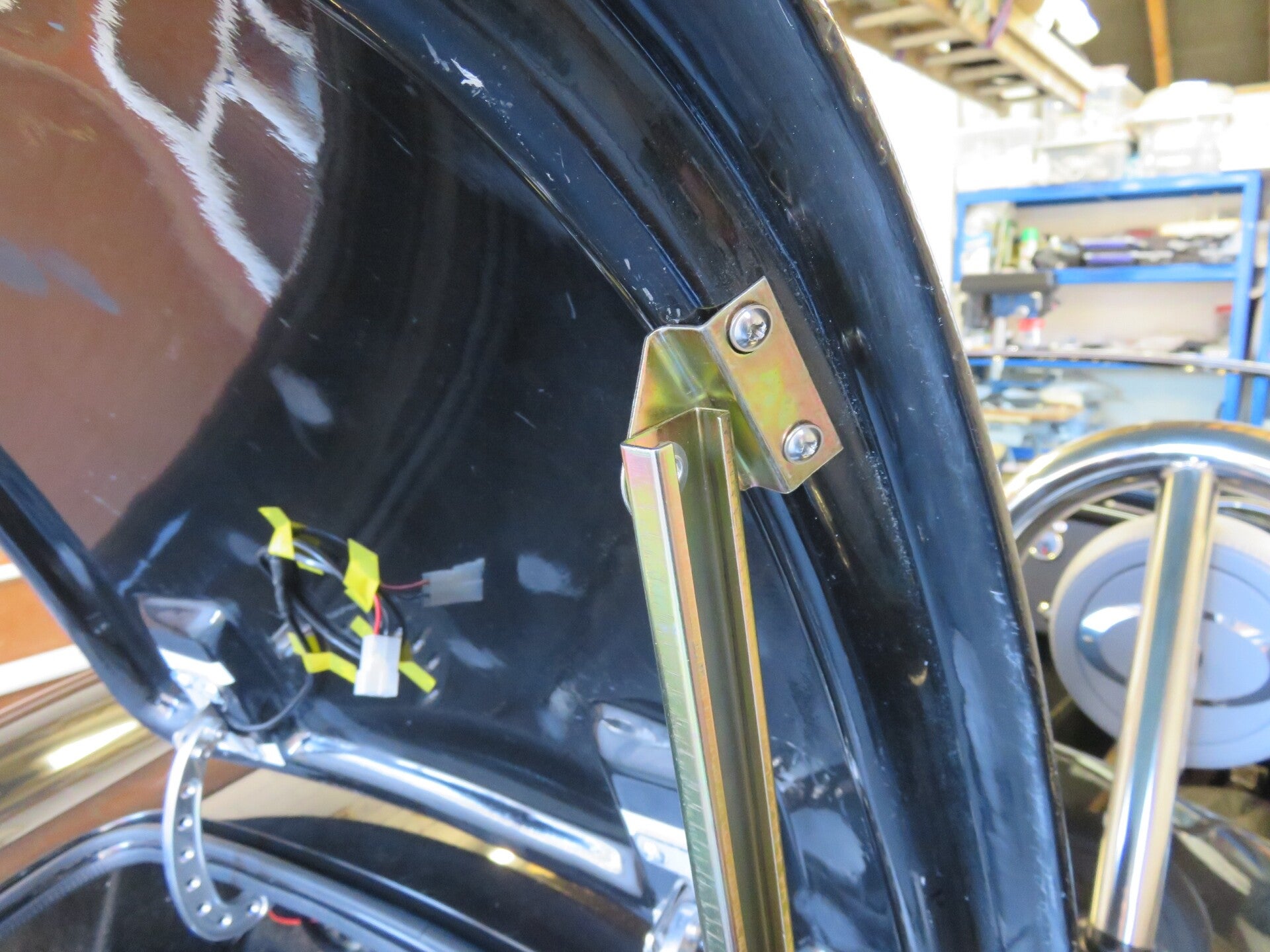
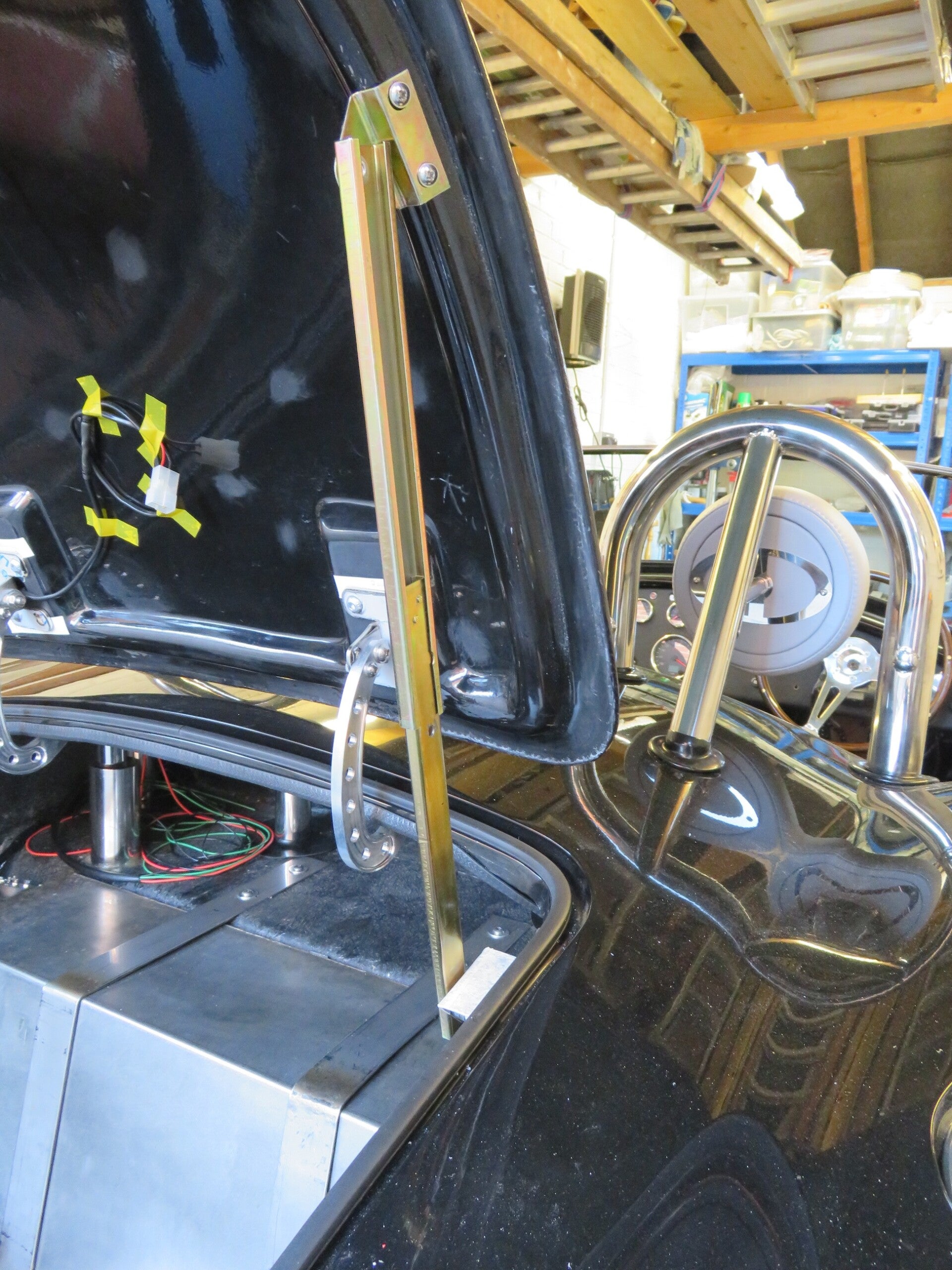
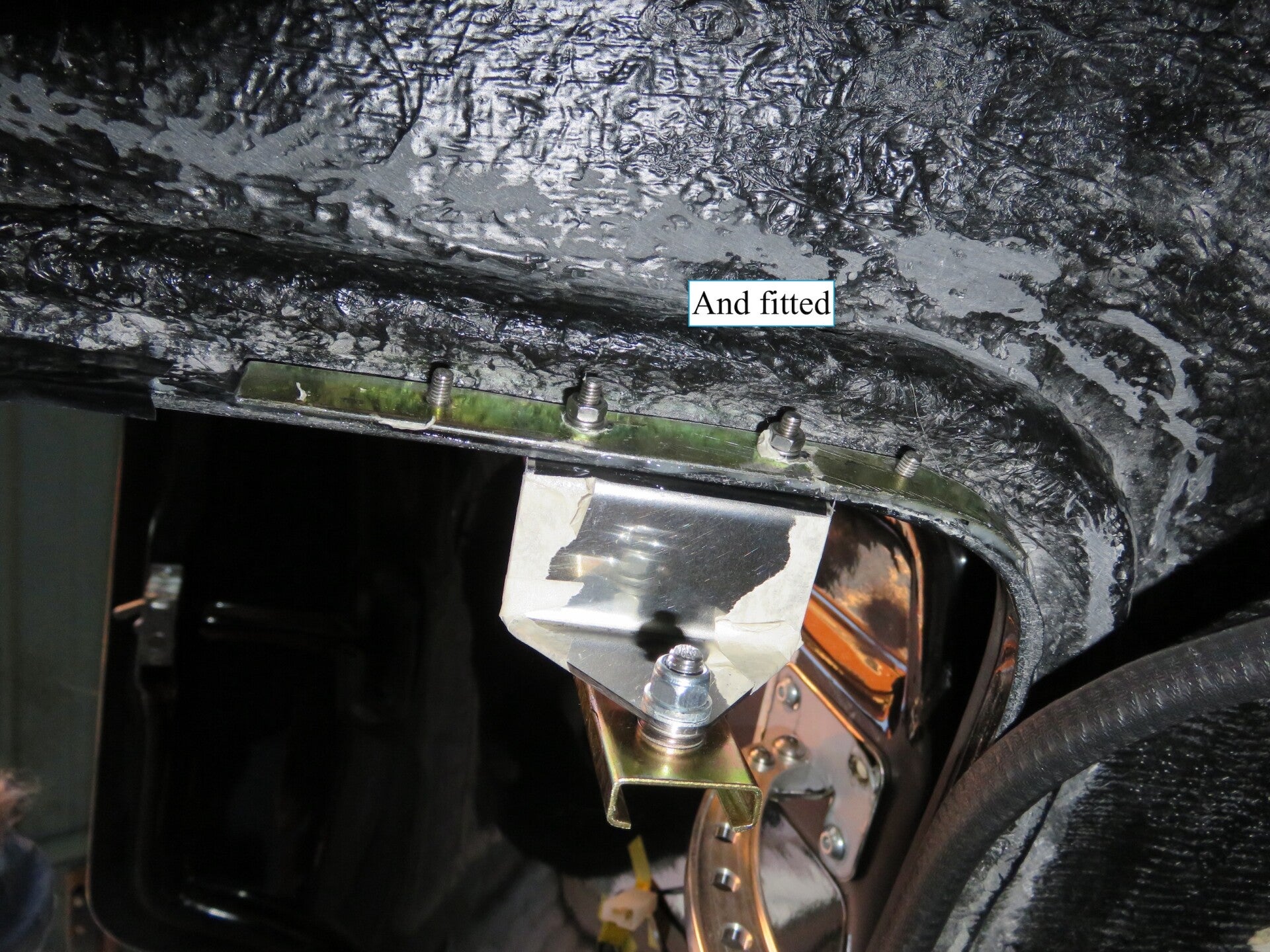
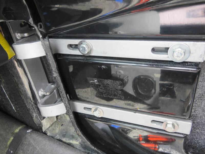
Boot Stay: Very fiddly job... To firm everything up a tad, I fashioned and contoured a piece of stainless steel "stiffener" around the inner lip. I fitted this to the inside edge to spread the load to minimise flexing.
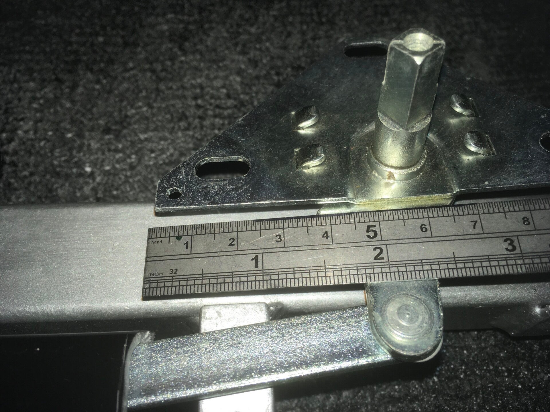
Now... In that theme, and because I didn't go for gas struts, i.e. one on each side, I got thinking about the positioning, the weight distribution and the stress at the lower fixing point... So I got the kitchen scales out, and I measured a 2.1 Kg downward force difference at various points just by moving [simulating] the fixing point by an inch or so. This value is the weight of the boot lid on the lip fixing points at different positions along the lip.
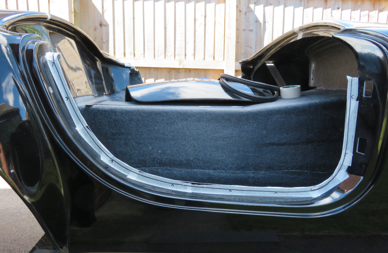
Hanging The Boot Lid… Roughly fitted the boot with no spacer/packing washers in place on the hinge bolts; this to make sure there was enough slop to move the boot around to centre it properly. I decided to do it this way because, with the boot [loosely] bolted in place, it was easier to line up and secure it in its proper place without having to faff around too much.
- Centred up the boot (rechecked with the latch in the closed position)
- Put a couple of corresponding marks on the body and boot as reference points
- Propped the boot open and measured, aligned and fitted some hinge-bolt spacer-washers where necessary
- Adjusted for flatness by altering the hinge angle, i.e. to get a smooth transition line between the boot lid and the shell
- Tightened everything up
- Job’s a good’un

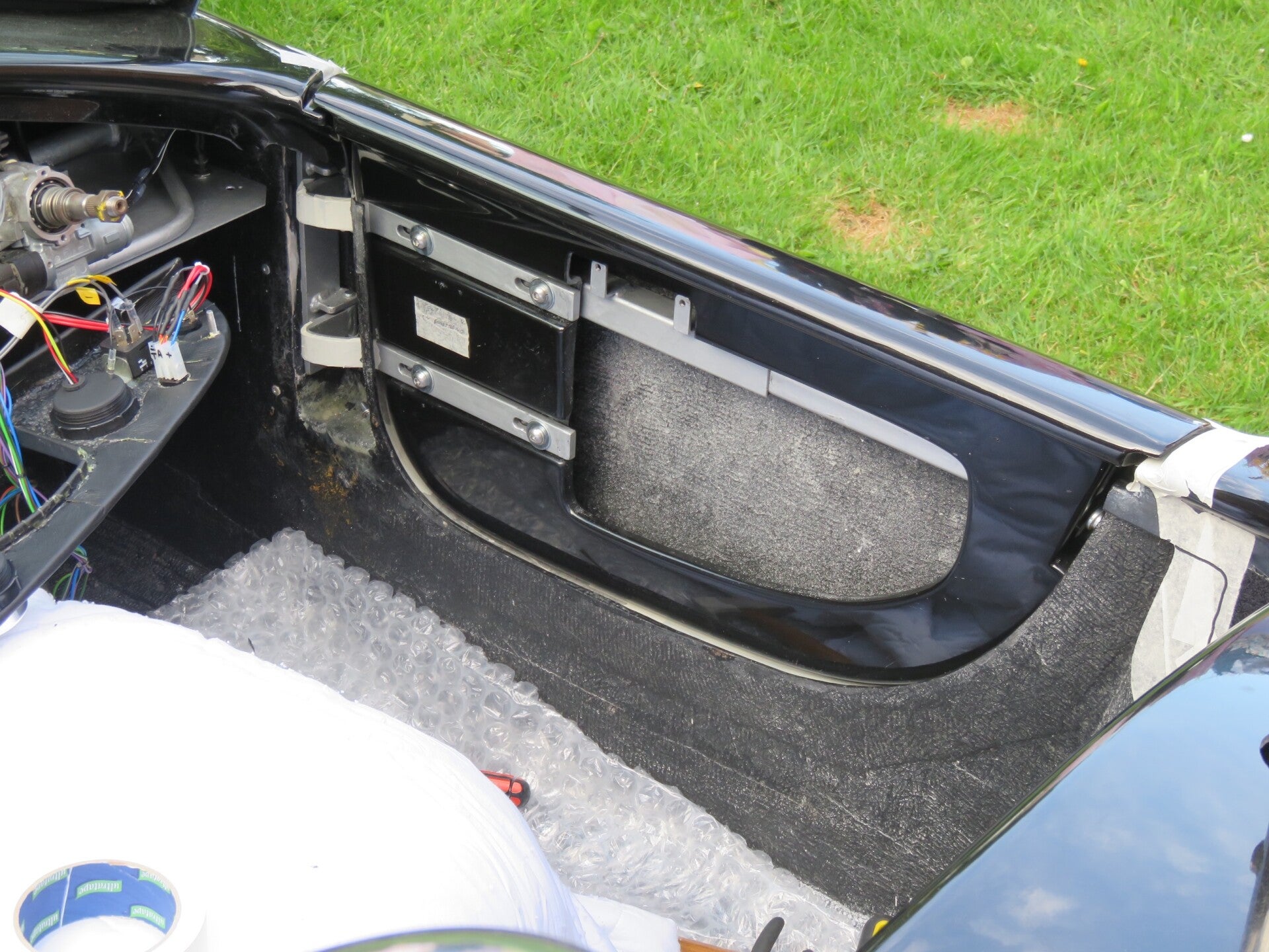
Boot/Bonnet Hinges
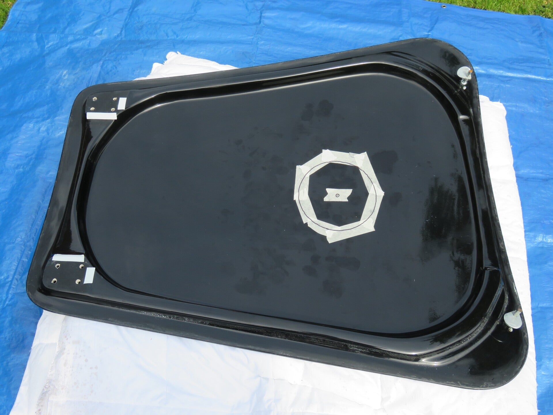
Fitting the boot lid was quite straightforward. Fixed the rubber seal in place, then lined up the boot edges on the outside (whilst I was inside with the tape measure, marker pen and a torch). Packed out the fixing positions with washers to centralise the boot, and bolted it in place.
Hinges: The hinges are a work of engineering art. Couldn't resist them. Quite a straightforward fitting; just trim the spacing flange to size, adjust the hinge spacing with packing washers, bolt them in place, attach the boot and adjust for flatness as necessary... Job done.
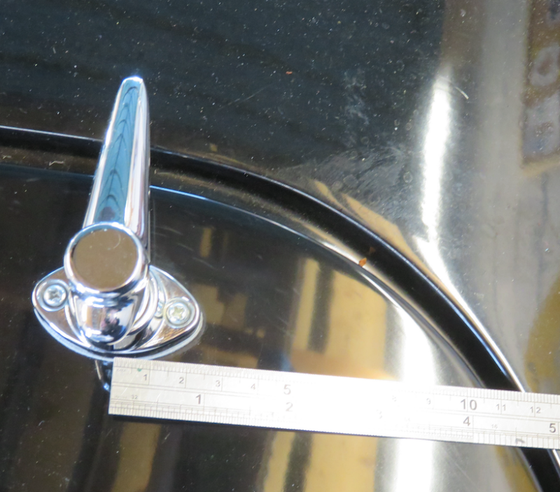
Boot Handle: Marked up for the boot handle and drilled and fitted. I did, however, use bolts, not the supplied self-tappers to secure it.
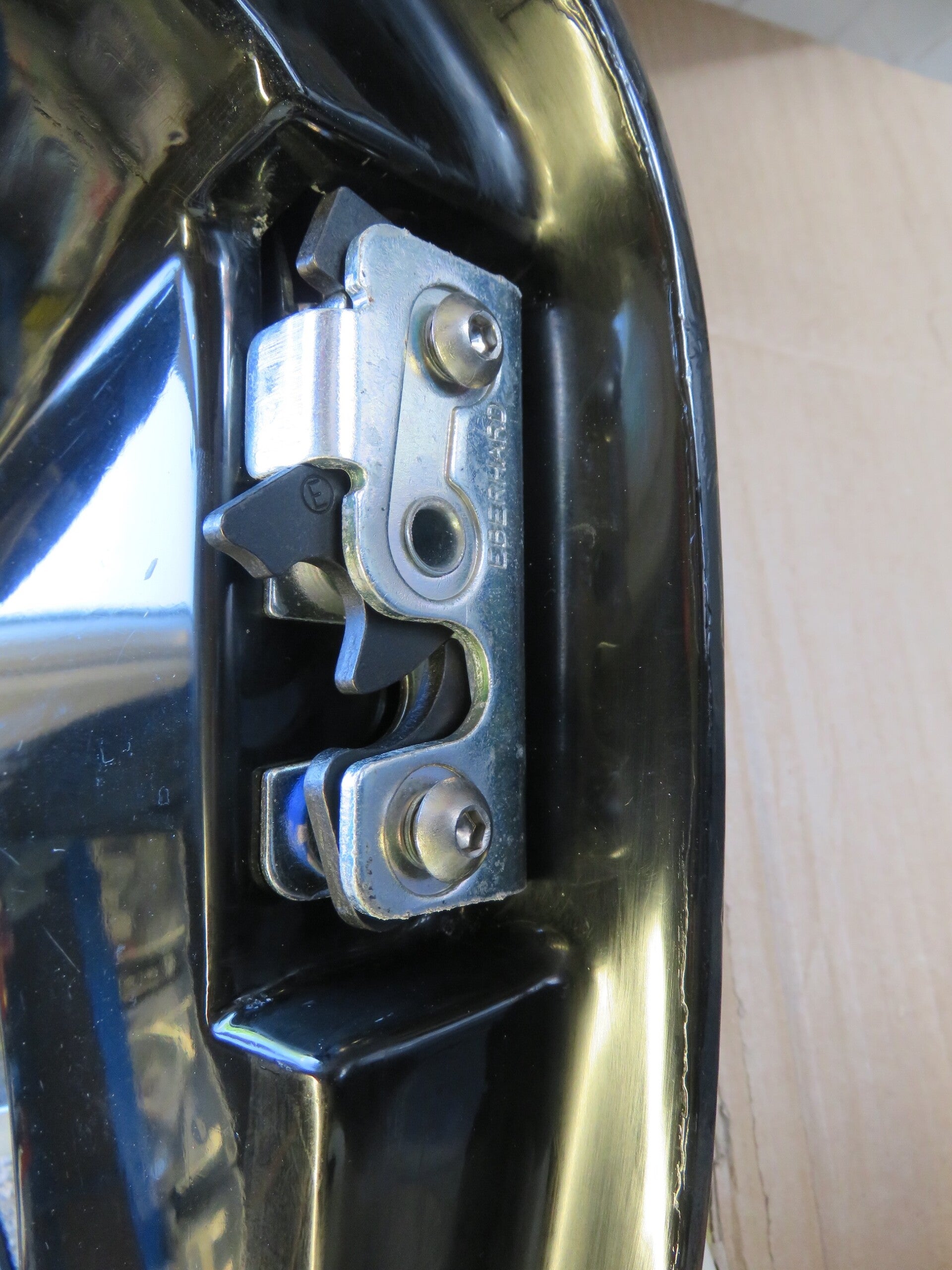
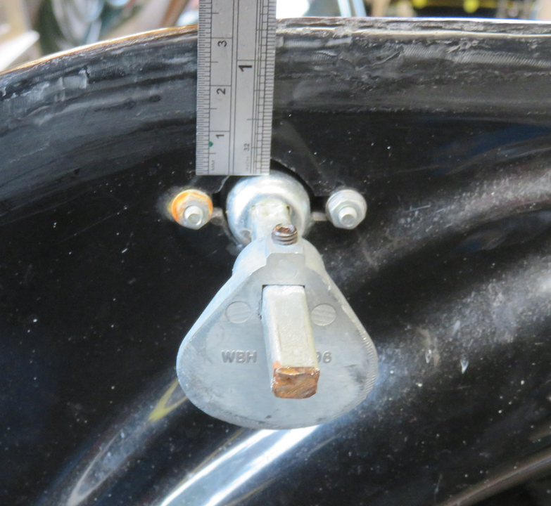
The Catch: Lying in the boot (again) with it closed. I marked up for the catch receiving plate, and again fitted it with bolts, not self-tappers.
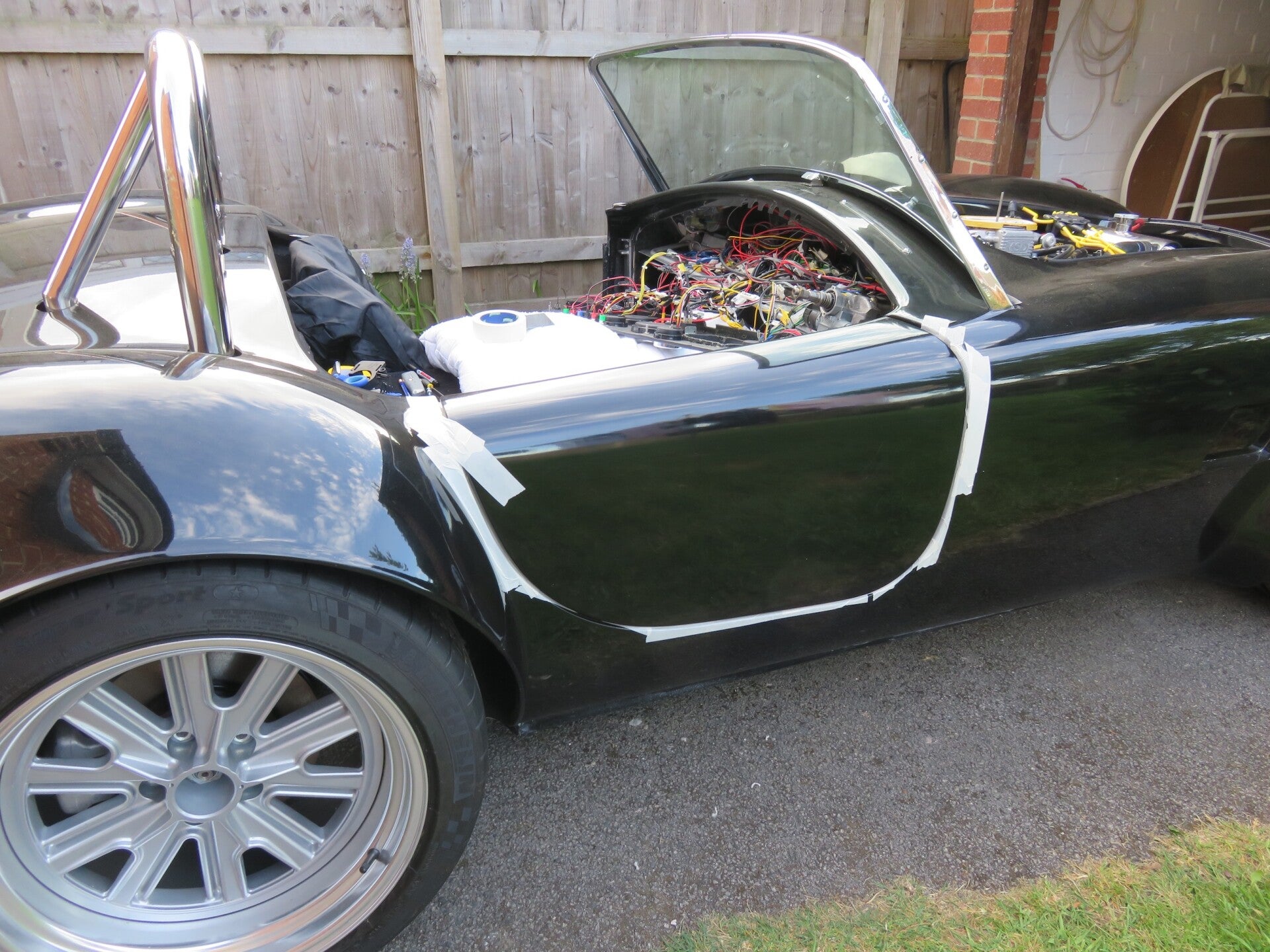
Bonnet Handles & Latches
Same procedure as for the boot; however, marking up without the engine in the way was a really good way to see what was going on.
Handles: Fitting the bonnet handles and latches was a bit fiddly (what isn't), but nothing too intricate that time and tea wouldn't resolve.
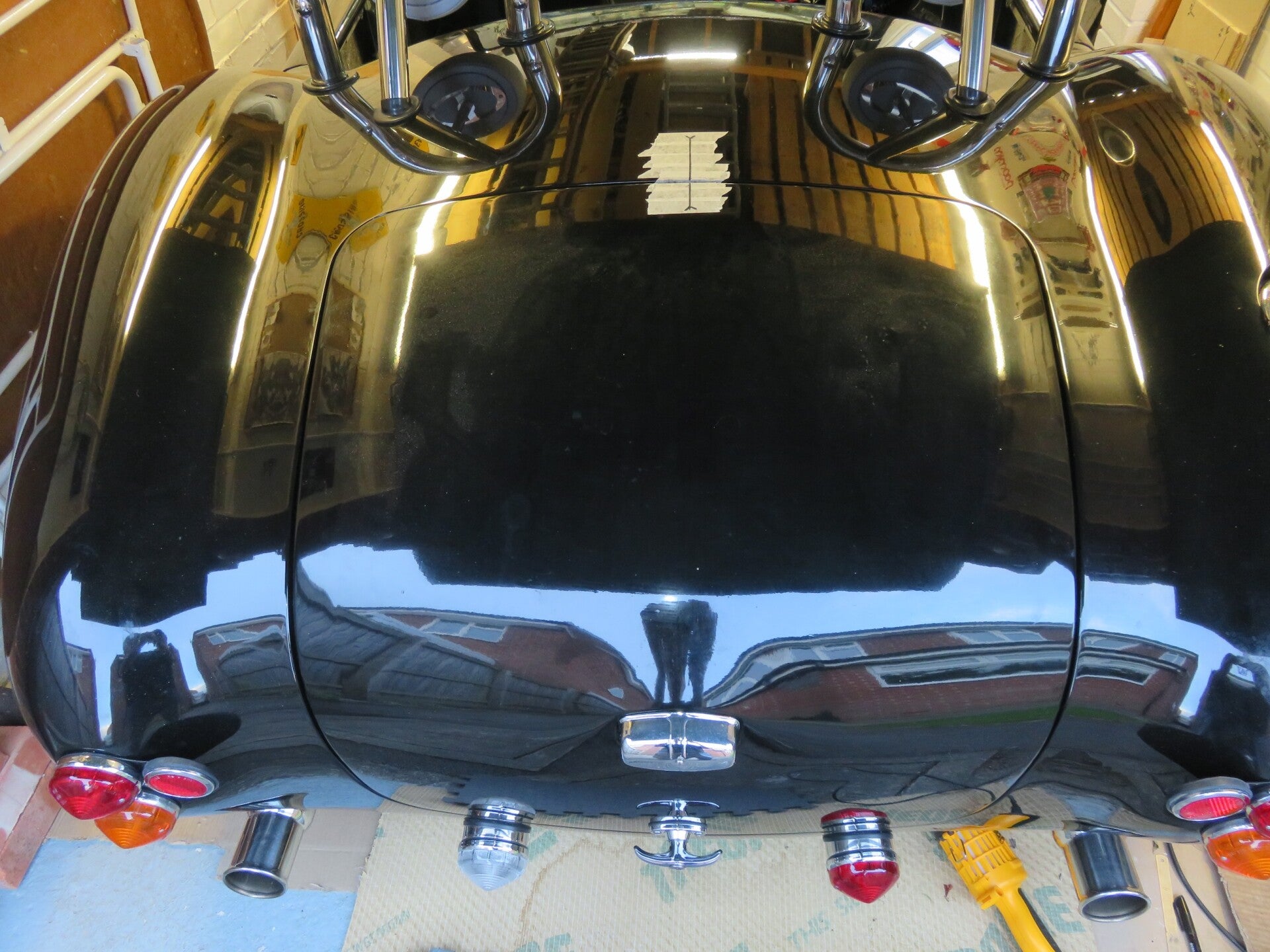
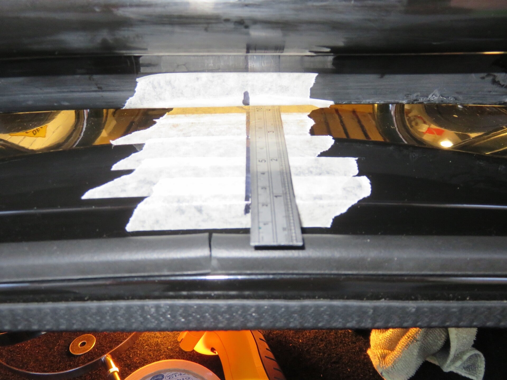
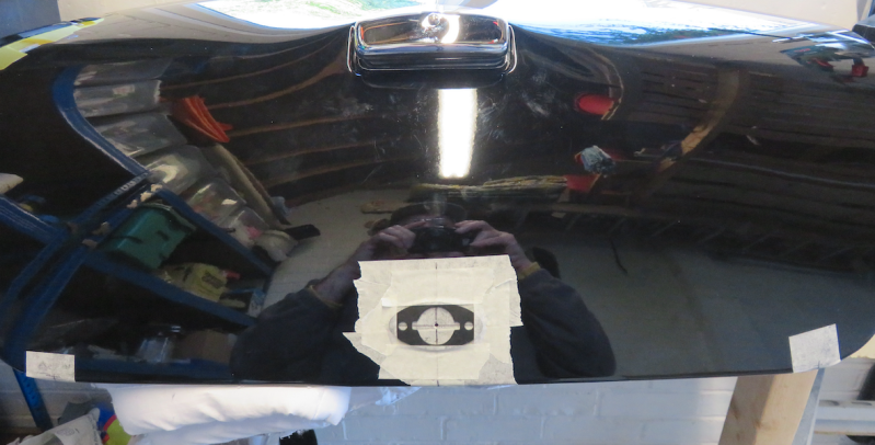
The first thing I did was to verify the bonnet drill markings made by GD. I did this by making a paper template (not a cardboard one). And not having any "golden" specific reference points that I could rely on as being good for both sides, I creased the paper around the curve of one corner of the bonnet and marked where the factory mark was. Then I used the same template (but flipped over) to see how far the other side's mark was 'off' with respect to the first mark... Spot on!
I could have faffed around measuring from the centre of the bonnet when lined up with the centre of the car, but that would have been complicated and fiddly. For this job, I essentially just needed to check that the two handles were in the same relative positions, the paper template marking method being foolproof for this type of measuring.
Masked up around the marker hole and marked the shape of the fibre gasket. Then I simply routed out the shape with the Dremel and finished it off with some hand filing.
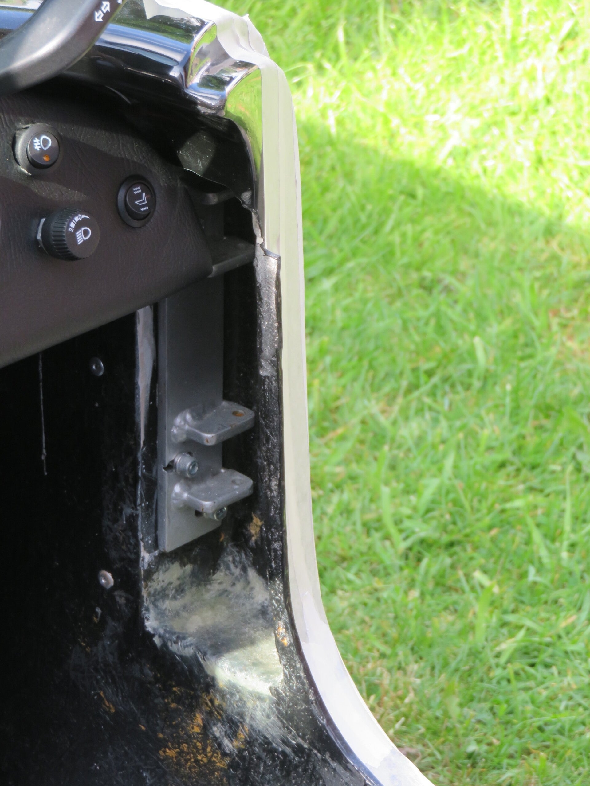
Catches: The bonnet catches were fiddly to fit, but this is one area (out of the many other areas on the car) that needed to be spot-on.
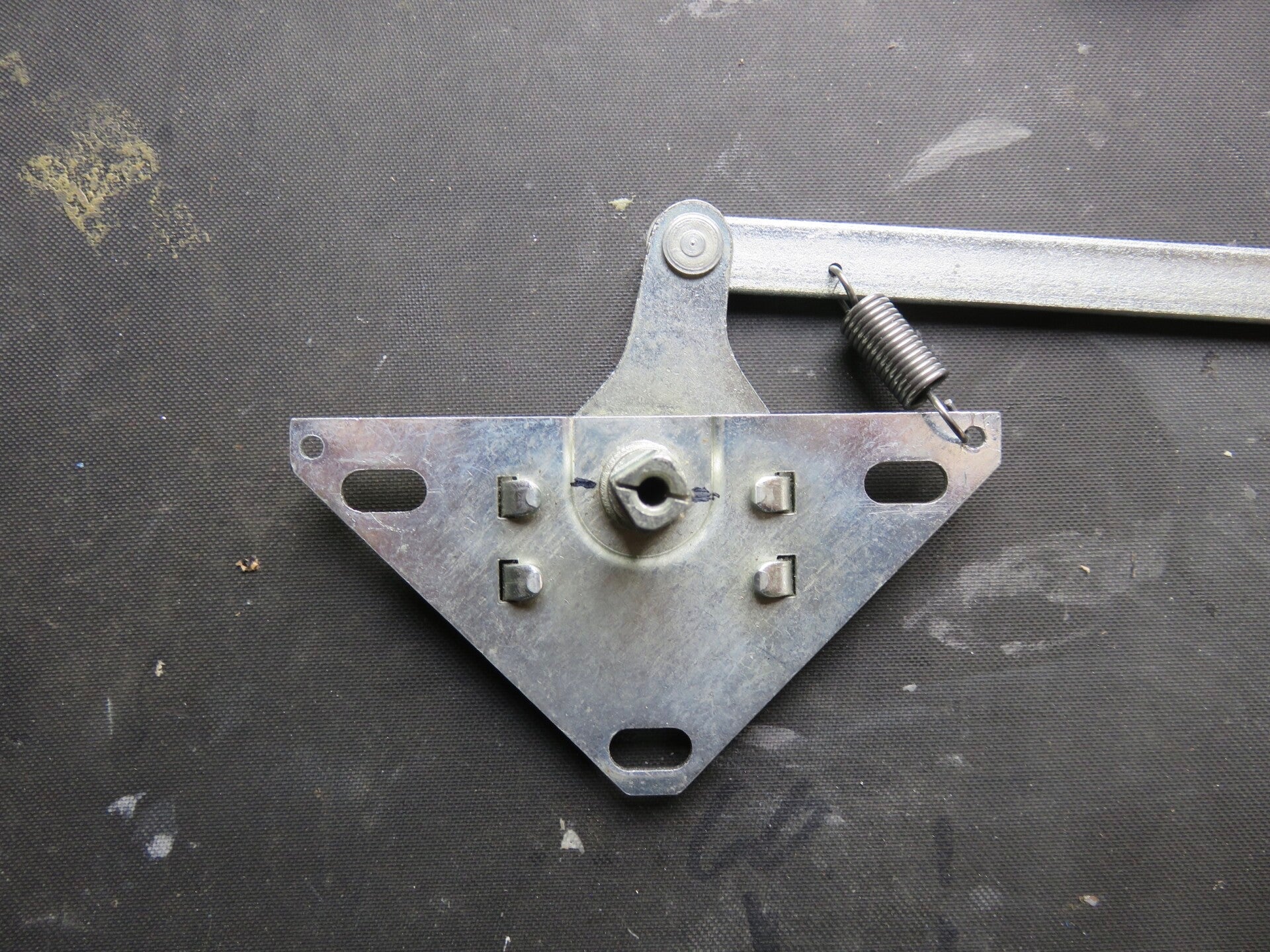
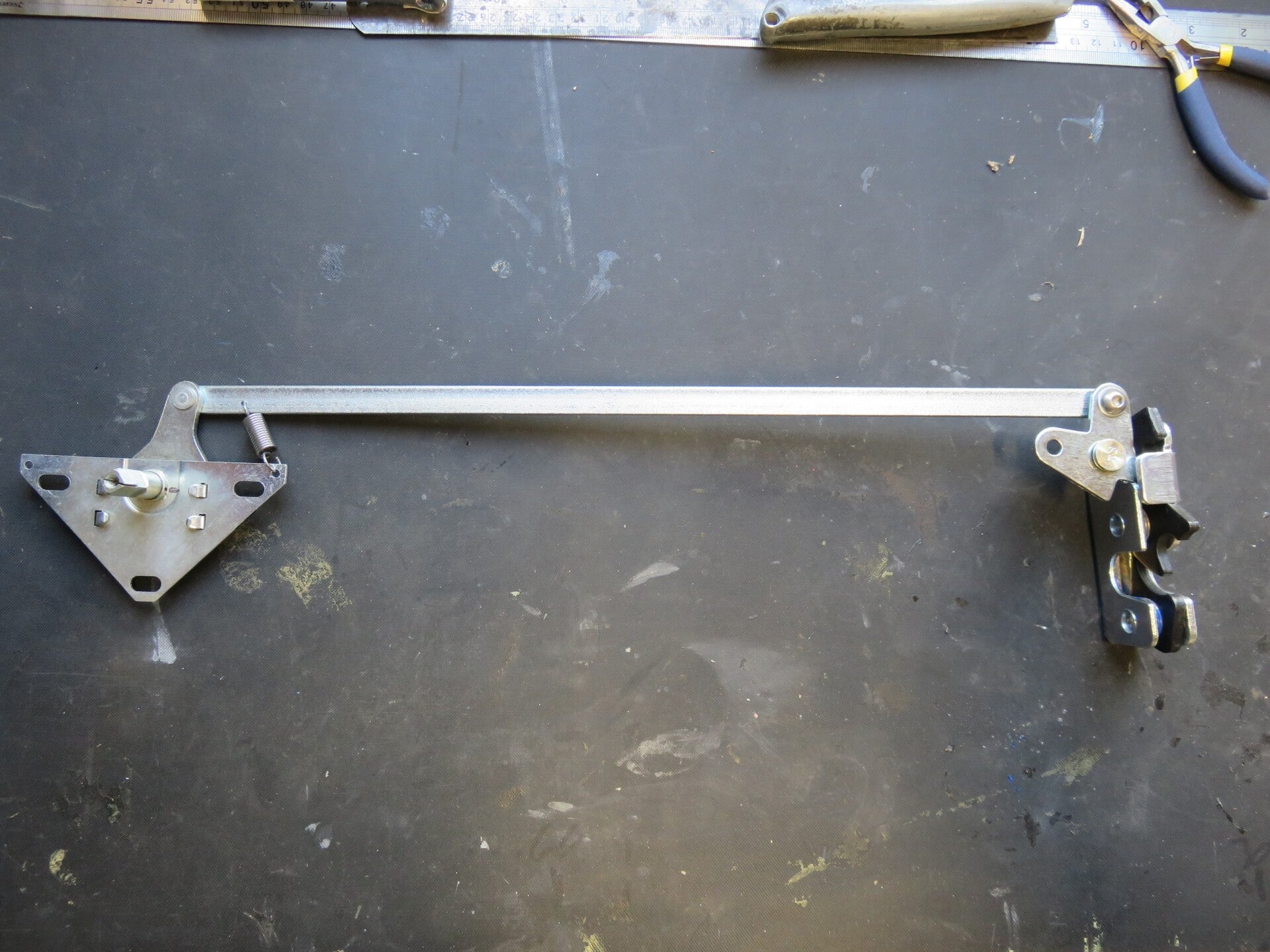
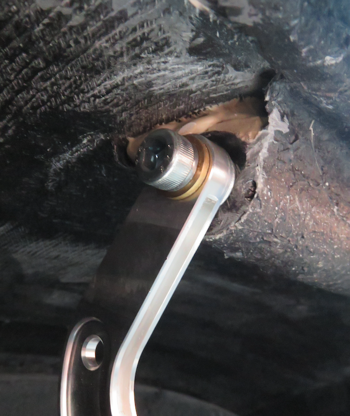
Marked up and drilled for the handles first, then fitted the square spindle bar and marked up to cut the key slot in the bulkhead for the cambered catch. Then, when everything was working nicely and smoothly, I cut the spindle bar stop to the correct length to make it look neat...
The last job was to put a rubber ‘D’ seal around the whole rim to stop water ingress into the engine area…